Shear Force Measured Under Patient's Hip on an I Inclined Bed-Juniper Publishers
Juniper Publishers-Journal of Robotics
Abstract
Shear force is measured under a patient's hip when he
is on an inclined bed. To do that, we need to develop an instrument.
That means to find a sensor and because it is expected that the shear
force is very weak the signal must be amplified so we have to design an
amplify, certainly we need a read out unit to indicate the measurement.
All these are given in detail in this paper. Through theoretical
consideration for a simplified model, a functional relationship between
the shear force and the inclined angle of the bed is also obtained. To
make it clear the explanation of friction, shear force and shear stress
is given in Appendix
Editorial
Patients occasionally required to be on an inclined
bed for certain therapy. One easily understandable therapy is to help
the blood circulation in the legs and feet. When a patient stays long in
a horizontal bed, often will have a muscle clamp in the legs. If the
bed can be adjusted to an inclined position the clamp can be stopped.
The shear force between his hip and the bed affects strongly how long
the patient can stay at that position and is expected to be a function
of inclined angle. Shear force is a familiar terminology for mechanical
engineers, but it may be not clear to layman outside engineering so a
detail explanation is attached in Appendix. Certainly it is good to know
exactly the force and the inclined angle how they are correlated. Our
project is simply to find that relationship.
There are many different possibilities for the
measurement. Search through the literature, we found that the closest
paper is done by RHM Goossens, it is entitled "Shear Stress Measured on
Three Different Cushioning Materials” [1].
This paper describes the shear stress measured at the patient's hip
sitting on an inclined chair for different cushion materials at three
different seat angles, 5° forward 5° backward and horizontal. Six
sensors were used, but there is no detail about the sensors except the
size. The measured results were about 4-7KPa for the shear stress. This
is not exactly what we need, however it shows the stress is in very low
value and sensors must be thin. Further search we find "Load Cell
Assembly” by Kroll et al. [2].
This is a Patient application. It describes the shear stress measured
by strain gages. From here we feel that strain gage may be a good
candidate for our measurement. Another paper entitled "Plantar Shear
Stress Measurements” by Rajalal, Lekkala [3] is a review paper, confirms that strain gage may be used for shear stress measurement.
Our Approach
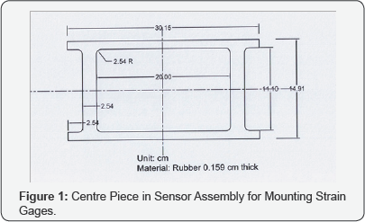
Since the shear force is based on the friction of
patient's hip on an inclined bed, it must be very small or say, it is
expected to be a fraction of a kilogram of force. So we choose strain
gages to be the sensor, and they are mounted on a piece of rubber with
the shape showed in Figure 1.
It is known that strain gages are not to be mounted on rubber, it will
not stay long. But because other materials will not produce the strain
to cause the sensor to react we do not have other choice. The shape is
specially designed in this way so that is strain is more in the webs
where the strain gages are mounted. Two strain gages are connected in
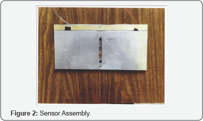
series so it will be more sensitive. This piece of rubber is mounted
between two pieces of stainless steel sheet, the top edge is attached to
the bottom plate and the bottom edge is attached to the top plate. The
stainless steel plates are loosely connected by a screw in the middle so
that two plates can be easily moved by the shear force. The whole
sensor assembly is 15.24 X 30.48 X 0.476 cm. It is thin enough; it can
be buried in the blanket of the bed. The picture of the whole assembly
is shown in Figure 2.
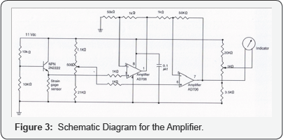
Since the shear force is low, the signal in the
strain gages is weak; in order to have readable output we must have a
good amplifier. A differential amplifier with IC AD706 is chosen for our
circuit. The constant current to the strain gages is supplied through
an NPN transistor 2N2222. If the whole signal of the strain gage is sent
directly to the amplifier, the output will be very high even the
amplifier with the limited gain. To solve this problem we build a
compensation circuit to balance the dc voltage output from the strain
gages. In this way only the increased voltage in the strain gages will
be amplified. High gain of 50 is chosen for the amplifier. Because this
instrument will not be used constantly, the part for dc voltage
measurement in a multi meter is used for the readout unit. The advantage
of using a multi meter is that its' sensitivity is automatically built
in, the most sensitive position is 0.6 v, next is 3.0v and then 12v. We
can easily ship the sensitivity when the output changes. To make the
reading stable near the zero, another compensation circuit is built for
the zero point adjustment. The whole circuit is shown in Figure 3.
The power is supplied from an adjustable voltage AC power supply and
rectified by a full wave bridge circuit with a complete filter. The
voltage at the input is 11 volts.
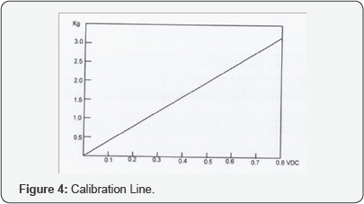
The instrument is tested to make it certain that the
performance is sensitive and stable. Then we calibrate the instrument. A
spring scale is used for the indication of the input force. The
calibration results are given in Figure 4.


Analysis
The analysis done in the following is much simplified
from the actual situation. The sensor is placed under the hip of the
patient but the patient lying down on an inclined bed, actually is
supported by upper body, hip and legs. The model considered here assumes
no connection between hip and other parts of the body. Because the
forces between hip and other parts are unknown and complicated. This
analysis certainly is overly simplified. However if we use three sensors
and all three parts of the patient's body are supported by sensors and
the results are added together. This analysis may be close to that case.
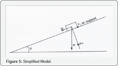
Consider that the weight of the block is W, the tangential component of the weight is Wt = W sinθ and the normal component of the weight is Wn = μW cosθ acting on the block in tangential direction is
FT = W sin θ - μW cos θ
If, FT < 0 , the block will not move, ifFT > 0 then the block will move down the slope.
 The tangential force acting on the inclined plane (shear force measurement sensor) is
Fshear = Ff =μW cos θ
To verify the above analysis, we did one measurement with the setup as in Figure 5. A piece of plywood is used for the inclined plane with θ = 170,
W = 2.73 kg. The shear force sensor is placed directly on the wood then
another piece of wood is placed on the sensor and books used as the
load, we had reading on the sensor of 0.25 V, from calibration Figure 4, it is found the shear is 0.90 kg. Because Wt = 0.8kg and Fshear = 0.9kg
. Hence the block is not moving. Consequently we find the friction
coefficient between wood and stainless steel is 0.345.This is a
reasonable number.


Comments
Post a Comment