Gyroscope Torques Acting on Rolling Disc- Juniper Publishers
Juniper Publishers- Journal of Robotics

Abstract
Recent investigations in gyroscope effects have
demonstrated that their origin has more complex nature that represented
in known publications. On a gyroscope are acting simultaneously and
interdependently eight inertial torques around two axes. These torques
are generated by the centrifugal, common inertial and Coriolis forces as
well as the change in the angular momentum of the masses of gyroscope's
spinning rotor. The action of these forces manifests the internal
inertial resistance and precession torques of gyroscopic devices. New
mathematical models for the inertial torques demonstrate fundamentally
different approaches for solving of gyroscope problems in engineering.
This is very important because the stubborn tendency in engineering the
increasing a velocity of rotating parts with different designs like
turbines, rotors, discs and other rotating components leads to the
proportional increase of acting forces that are expressed on their
motions in space. This work considers a typical example of computing the
action of internal inertial torques acting on the running disc.
Keywords: Gyroscope theory; Torques; Motions; Forces Introduction
Most of the textbooks of machine dynamics and books
that dedicated to gyroscope theory content typical examples with solving
of gyroscope effects [1-3]. Practice demonstrates the known mathematical models do not match the actual forces and motions in these devices [4,5].
Recent investigations into the physical principles of gyroscopic
motions have presented new mathematical models of forces acting on a
gyroscope [6,7].
The action of the external load on a gyroscope generates several
internal resistance and precession torques based on the action of the
inertial forces. Resistance torque is generated by the action of the
centrifugal and Coriolis forces of the gyroscope's mass elements. The
precession torque is generated by the action of the common inertial
forces of the gyroscope's mass elements and by the well-known torque
that is generated by the change in the angular momentum of the spinning
rotor. These resistance and precession torques act simultaneously and
interdependently and are strictly perpendicular to each other around
their axes. Equations of internal torques are shown in Table 1 [6].
Table 1 contains the following symbols: J is the rotor's mass moment of inertia around the spinning axle; ωi is the angular velocity of the precession of a spinning rotor around axis i and
is ω the angular velocity of a spinning rotor. The following
analysis ofthe actions of several torques and motions around the two
axes has used the system ofsubscripts signs. All components of the
equations are marked by subscript signs that indicating the axis of
action. For example, Tr.x is the resistance torque acting around axis ox , ωy, is the angular velocity of precession around axis oy , etc.

A different type of the free rolling flat cylindrical
type objects as a bicycle wheel, rims, hoops, discs, etc., possess
gyroscope properties. Generally, this rolling motion is considered as a
flat motion that more complex than simple spinning of the gyroscope, and
its mathematical treatment is considerably more complicated. However,
free rolling of the inclined cylindrical disc on the flat surface,
possess inherent the gyroscope effects that influence on the motion of
the rolling object. This work presents the mathematical model for
motions of the tilted rolling disc on the flat surface.
Methodology

The simple bicycle wheel or thin disc is unstable on
the vertical plane, but rolling motion demonstrates its stability and
steering itself in case of the disc tilts. This tilts leads to turn the
rolling disc in the direction in which it started tofall. This motion of
the thin disc is the demonstration of the gyroscope effects which
presented by the action of centrifugal, common inertial, and Coriolis
forces and the rate change of the angular momentum of the rolling disc.
These forces enable to bring the disc back to a vertical position and
allow it to roll onin right way or the new direction that resulting of
the disc new tilt.
To study the motion of a rolling thin disc on the
flat surface, it is assumed that thin disc is rolling with constant
angular velocity. Figure 1
represents rolling disc that slightly tilted in its path on the flat
surface. This slight tilt causes it to travel temporarily in a curved
path. Analysis of the motion of the free rolling thin disc on the flat
surface is considered with starting condition when the disc is
perpendicular to the surface. The thin disc of the mass of 0.5kg with
the radius of 0.2m, rolling with the linear velocity 1.0m/s and getting
the tilt of 100 from the vertical line as shown in Figure 1.
It is necessary to find the internal torques, exerted on the rolling
disc and its precessions. The inclination of the rolling disc generates
the following torques:
• The resistance torques based on the action of the centrifugal Tctx and Coriolis forces Tcrx acting around axis ox .
• The precession torques based on the action the change in the angular momentum Tamx of the rolling disc and the inertial forces Tinx acting around axis oy .
• The resistance torques based on the action of the centrifugal Tctx and Coriolis forces Tcrx acting around axis oy .
•The precession torques based on the action the change in the angular momentum Tamy and the inertial forces Tiny around axis ox .
The precession torques turn the rolling disc to the
direction of the tilting and the disc rolls by the curve path with the
radius L .The curvilinear motion of the disc generates the action of the
centrifugal force acting horizontally and creating the torque about the
contact point of the disc with the surface. This torque acts in the
same direction as the resistance torques and altogether bring the disc
back to a vertical position. From the data presented above is defined as
the angular precession of the disc around axis at starting condition.
The equations of the torques balance around axis and are represented as
follow:
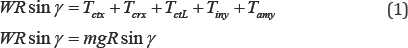
where WRsinγ = mgR sinγ is the action of the disc's weight to its incline; is the mass of the disc; g is the gravity acceleration; R is the radius of the disc; Tctx and Tcty are the resistance torques generated by the centrifugal forces; Tcrx and Tcry are the resistance torques of the Coriolis forces and acting on the rolling disc around axis and respectively; Tamx and Tamy
are the precession torques generated by the inertial forces and and are
the torque generated by the change in the angular momentum of the
rolling disc acting about the axis ox and oy respectively (Table 1); TctL is the torque generated by the centrifugal forces of the rolling disc by the curve pass with the radius L . From Eq. (1) is removed the torques of centrifugal and inertial forces acting about the axis oy as selfcompensated [7].
The disc is rolling on the curve pass generates the
centrifugal force and hence the torque acting about the point of the
disc contact with the surface. This torque is defined by the following
equation:
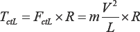
Where is the centrifugal force generated by the rolling disc, other parameters are as specified above.
Substituting defined parameters into Eq. (1) and transforming yield the following equation:

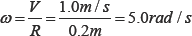
Where j = mR2/2 is the mass moment of inertia of the disc, ω = V/R is the angular velocity of the disc, V is the linear velocity one, other parameters are as specified above.
The angular velocity of the disc is defined by the following equation:
The angular velocity of precession about the axis oy is defined by the following equation:
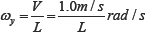
Where L is the variable radius of the disc motion by the curvilinear path.
Substituting defined numerical data of the initial
parameters into the first equation of Eq. (2) and transforming gives the
following equation of the angular precession about the axis ox
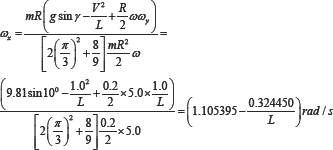
The velocity of the angular precession ωx about the axis ox is variable and depends on the radius of the curve pass L . When the L = (0.324450/1.105395) = 0.293m then ωx= 0 , i.e., the torques acting around axis ox in balance and the disc is rolling by this curve pass without fall. Change of the radius L
leads to change of the magnitudes of the centrifugal force and
precession torques acting on the disc rolling. Increasing of the linear
velocity for the rolling the disc leads to its vertical location and
decreasing velocity leads to falling of the disc.
Results and Conclusion
New analytical approach to the gyroscopic devices
enables developing the equations for the forces and motions of any
rotating objects moving in the space. The mathematical models for the
rolling disc motions based on the action of the centrifugal, common
inertial and Coriolis forces, as well as by the change in the angular
momentum. The action of these forces is interrelated and occurs at one
time in the gyroscopic devices. The new analytical approach to gyroscope
problems demonstrates and explain the physical principles of acting
forces on a gyroscopic device and its motions. The mathematical model of
the rolling disc motion on the flat surface are validated the gyroscope
properties by practical observation and represent a good example of the
educational process.
For More Open Access Journals Please Click on: Juniper Publishers
Fore More Articles Please Visit: Robotics & Automation Engineering Journal


Comments
Post a Comment