Real-Time Visual Subject Tracking and Classification by Combining Motion Signal Analysis andTridimensional - Shape Feature Classifiers with Group-Induction Boosting Algorithms- Juniper Publishers
Juniper Publishers- Journal of Robotics

Abstract
This paper provides a novel and unprecedented
approach for integrating motion features in the detection and
classification of moving subjects in a static environment. More
specifically, we measure the impact of the use of trajectory history,
rotation history, blob orientation, motion frequency in the three axes,
motion acceleration, segmentation errors, and flickering scores, and how
they can influence classification of moving people, pets, and other
objects. We apply our method to data captured by a combined color and
depth camera sensor. We find that, while some motion descriptors
slightly improve accuracy, the use of them in conjunction outperforms
previous approaches in the classification and tracking of real-world
moving subjects in real-time.
Keywords:
Real-time tracking; Moving subjects; Classification; Motion signal;
Motion statistics; Accelerometer; Orientation; Rgbd camera; Depth
images; Computer vision; Machine learning; Classifiers; Boosting;
Artificial intelligence
Introduction
Many home security products that are available on the
market promise to detect intruders at home and notify users via text
messages. However, these home surveillance platforms often have high
rates of false-positives and low tolerance for them. In other words, the
user often receives messages because their pet walked in front of the
camera or the wind moved the curtains. The user then grows accustomed to
these false alarms and therefore ignores any future alarms that could
be real threats. Furthermore, when a user wants to play back and watch
all indoor moving subject activities, he has to watch all of the
false-positive parts of the footage as well, wasting countless hours of
time. Other potential uses of home cameras are harmed by the fact that
the recognition technology is solely based on naive movement detection.
Our approach uses depth cameras, as well as
accelerometers and gyroscopes to easily place the camera on the wall and
detect its orientation, create a point cloud or tridimensional
representation of the moving subjects, and use statistics and machine
learning to more accurately detect and predict the nature of the moving
object (Figure 1).

We also use a group induction1 method
(inferring object type based on close similarity to a labelled object,
or geographical proximity to it), which allows us to use smaller amounts
of human labelling than similar conventional approaches. Moreover, our
results are compatible with semisupervised
learning techniques (meaning we can allow a user
to label only a few examples, and we infer the rest from that)2.
This method enables the user to train the algorithm in a more
practical manner, since a customer will often not take the time
to label all data, but will agree to label a few of the data points
(for example, the false-positives or false-negatives) [1].
Foot Note:
1Because our point clouds are grouped
into animations, including multiple frames, all those frames can be
labelled as part of the same object, assuming that the object was
appropriately tracked. This can help with training the predictors with
more data.
Source: Teichman, Alex, and Sebastian Thrun.
“Group induction.” 2013 IEEE/RSJ International Conference on Intelligent
Robots and Systems. IEEE, 2013.
Yoctopus accelerometer+gyroscope sensor. We added this
accelerometer and gyroscope to the depth camera sensor, in
order to programmatically determine its orientation with
respect to the horizontal ground plane (Figure 2).

This is what the depth camera and the IMU sensor look
together3 . The project also involved a heat sensor (green) but
the results of the heat descriptors are reported in a separate
paper [2] (Figure 3).

Background
We used a model built originally for a project dealing
with self-driving cars. The model involves a boosted learning
classifier based on Adaboost, and the innovative use of groupinduction
as a method of semi-supervised learning. Although
some tests and development were performed with semisupervised
learning, for the most part of the project, and for
our research results, we decided to use a fully-supervised
model so as to eliminate any possible noise, mislabelling or bias
introduced by the use of semi-supervised learning4. (Figure 4).

The data we were working with is originated from a
PrimeSense RGBD depth camera (color+depth), to which an
accelerometer and gyroscope have been added. The depth
image captured from the sensor is used to create a statistical
model of the background or environment, which is static. When
a part of the image is statistically outside the range of what
constitutes the static background, that section is likely to be
marked as an object in the foreground. That object is then
converted into a point-cloud to more pragmatically represent
the data. It is processed throughout our pipeline or saved for
later processing5.
Foot Note:
2Although our research results are
compatible with this semi-supervised boosting, we have preferred to use
fully supervised learning to generate
the results for this paper.
Source: Teichman, Alex, and Sebastian Thrun.
“Tracking-based semi-supervised learning.” The International Journal of
Robotics Research 31.7
(2012): 804-818.
3We used an intertial measurement unit, which performs sensor fusion of the data gathered by an accelerometer and gyroscope.
Source: Morrison, Melvin M. “Inertial measurement unit.” U.S. Patent No. 4,711,125. 8 Dec. 1987.
4We are using the algorithm developed by
Alex Teichman in order to classify tracks of all moving objects, instead
of tracking a specific class. This
method is non-specific to object class.
Source: Teichman, Alex, and Sebastian Thrun.
“Practical object recognition in autonomous driving and beyond.”
Advanced Robotics and its Social
Impacts (ARSO), 2011 IEEE Workshop on. IEEE, 2011.
5We use the depth-image segmentation method created by Alex Teichman and Jake Lussier.
Source: Teichman, Alex, Jake T. Lussier, and
Sebastian Thrun. “Learning to Segment and Track in RGBD.” IEEE
Transactions on Automation Science
and Engineering 10.4 (2013): 841-852
Machine Learning Algorithm
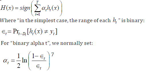
The classification technique we have decided to use for this
experiment was that of the boosting technique6. “Boosting
refers to a general and provably effective method of producing
a very accurate prediction rule by combining rough and
moderately inaccurate rules of thumb” in the following manner
[3,4]:
This algorithm is fast and has many tweakable parameter.
It is also suitable for the processing of a large list of descriptors.
The technique uses an array of weak learners that complement
each other to improve overall performance.
Descriptor Pipeline
Our descriptor pipeline takes the point cloud animations,
which consist of a series of frames that represent moving
objects. These frames have point cloud stills in them. Together,
all point clouds for all frames in the animation constitute one
instance.
Each frame of the instance (each point cloud) is pushed
through the descriptor pipeline individually, even if these
individual images correspond to the same instance of the
object being observed [5].
As seen on Figure 5, the data travels from Blob Entry Point,
the input node, then goes into Blob Projector, which projects
the RGBD data from a pixel matrix containing depth and color
values into a 3D point cloud, a list of points (X, Y, Z pairs) with
color values (R, G, B). Then, the data is sent into two different
pods (nodes): HSV Histogram, where the RGB colors are
converted into the HSV space8, and then a color histogram is
computed. The color histogram has H, S, V values for each bin
in the histogram [6].


Foot Note:
6We use the boosting technique for our machine learning purposes.
Source: Schapire, Robert E. “The boosting approach
to machine learning: An overview.” Nonlinear estimation and
classification. Springer New York,
2003. 149-171
7From this paper:
Source: Schapire, Robert E. “The boosting approach
to machine learning: An overview.” Nonlinear estimation and
classification. Springer New York,
2003. 149-171.
8Data in the vector space are converted into space.
Source: Smith, Alvy Ray. “Color gamut transform pairs.” ACM Siggraph Computer Graphics 12.3 (1978): 12-19.
All these individual scalar values are then sent as a list
to the descriptor aggregator, which appends them to a list of
values for other descriptors.
Projected Size, a pod in which the 3D size is measured and
sent to the Descriptor Aggregator pod (at the bottom) in order
to append it to the list of descriptors to be computed by the
machine learning algorithm9. T his existing pipeline allows us
to add more descriptors and experiment with how they affect
classification results.
Other pods/nodes are found as well. We can see another
node is CloudOrienter, which transforms the point-cloud and
orients it based on its longest axis using the PCA algorithm.10
Once oriented into its principal components (X is the longest
axis, Y the second longest, and Z the last one), the point cloud
can be better aligned w ith previous images of t hat object. For
example, if the camera is observing a pen, it will be aligned on
its longest axis, so that it can be compared with other images of
a pen no matter their perceived orientation [7].
Then, the oriented pointcloud is projected onto multiple 2D
images (different planes: XY, YZ, and XZ) so that we can run a
HOG algorithm on each of them.11,12
Then, the results are condensed into a lower-density vector
so that the values can be aggregated and sent to the machine
learning algorithm [8] (Figure 6).

Foot Note:
9We use the boosting technique for our machine learning purposes.
Source: Schapire, Robert E. “The boosting
approach to machine learning: An overview.” Nonlinear estimation and
classification. Springer New York,
2003. 149-171.
10 Principal component analysis is an
algorithm that transforms data points that seem to be correlated into
linearly uncorrelated sets of values
(principal components). Thus, the variables that are most correlated for
the main axis, with other orthogonal axes accommodating the following
most
correlated sets of variables.
Source: Wold, Svante, Kim Esbensen, and Paul
Geladi. “Principal component analysis.” Chemometrics and intelligent
laboratory systems 2.1-3 (1987):
37-52.
11Histogram of Oriented Gradiates is an
algorithm that is often used as a feature descriptor for computer vision
tasks in order to detect objects. It was
used with a lot of success to detect humans in 2D images.
Source: Dalal, Navneet, and Bill Triggs.
“Histograms of oriented gradients for human detection.” 2005 IEEE
Computer Society Conference on Computer
Vision and Pattern Recognition (CVPR’05). Vol. 1. IEEE, 2005.
12HOG algorithm steps.
Method
We placed a Prime Sense RGBD camera near the roof of a
room and recorded dozens of hours of footage of activity in the
room. We attached an accelerometer and a gyroscope sensor
to the camera so that we could later re-orient the point clouds
based on the gravity vector measured by the sensors. People,
pets and other objects moved throughout the room and were
recorded and extracted from the background. These blobs
were then separately saved into an SD card. The data was then
manually labeled (per instance) using a C++ tool. The data was
then passed through the descriptor pipeline [9].
Then, we continued in the process to perform k-fold crossvalidation
(this process that enables us to reduce overfitting,
so that our classifier can generize better - learn to recognize
objects that are not that similar to the training examples). The
training data was divided into K chunks and the classifiers were
trained on K-1 chunks. Then, the classification and predictions
for the remaining chunk were compared against the ground
truth that was manually assigned to each instance, and the
accuracy values, among others, were computed and saved.
We divided moving objects into multiple classes: cat,
person, door, bush, and background, and then we performed
5-way classification. As we can see in the results, there were
generally mild improvements as we kept computing new
descriptors.
Pipelines Studied
As seen in Figure 6, the Base was the previously existing
descriptor pipeline, which orients the point clouds for objects based on their major components and aligns every object on such
axes. The Gravity pipeline is the same as the Base descriptor
pipeline, but we started aligning objects vertically, based
on the camera orientation (measured by the accelerometer
and gyroscope). As we can see, performance increases after
aligning objects based on the gravity-vector measurement.
We can see the Gravity pipeline in Figure 7. Then, Oriented
Trajectory is a pipeline to which we also added a trajectory
pod, which computes the object velocity and acceleration
in X, Y and Z coordinates, aligned with the gravity vector as
Z-down. This pipeline can be seen in Figure 8. Finally, since the
X and Y orientation is based on the object shape rather than
its environment, its use is irrelevant to motion statistics, and
thus it cannot be reliably used. Therefore, we added the Plane
Trajectory descriptors, which add a vertical speed feature, a
horizontal speed feature (on the XY plane), and it also computes
and sends the vertical acceleration and horizontal acceleration
scalars to the machine learning algorithm. This pipeline can
be found in Figure 9. Then, we added mean angular velocity
and acceleration, in Figure 10 (Rotation Statistics). Later, we
included a change rate estimator that measures the change of
the pointcloud between different frames of the moving object
(Figure 11). And finally, we added a Fourier transform node to
filter the spectrum of these motion statistics (Figure 12).
Base pipeline (Figure 5)
The base pipeline provides a functioning machine learning
architecture that very accurately predicts the class of the
moving object. However, in our studies, we will modify and
add to this pipeline. As we can see here, the point cloud is sent
through the CloudOrienter for most subsequent operations.
This will be different in the following modified pipelines.
The CloudOrienter rotates a point cloud in order to align its
longest component with the X axis, and the following longest
orthogonal axis on Y, leaving the remaining orthogonal axis to
Z.13 (Figure 5.1)
Gravity pipeline (Figure 7)
The Gravity pipeline is an enhanced version of the Base
pipeline, and includes a Gravitational CloudOrienter as the
main node. Instead of orienting point clouds based on the
object’s dimensions, this node orients them based on their realworld
orientation with respect to the environment’s vertical
axis. In other words, it uses the measured gravity vector (via
accelerometer+gyroscope) to orient the clouds vertically [10].

The object is oriented vertically based on the IMU sensor
that we attached to the depth camera. The Z axis (blue) aligns
vertically, with the measured gravity vector.
It is also rotated so that its principal component aligns with
the X axis (red) (Figure 7.1 & 7.2).
Foot Note:
13Principal component analysis is an
algorithm that transforms data points that seem to be correlated into
linearly uncorrelated sets of values
(principal components). Thus, the variables that are most correlated for
the main axis, with other orthogonal axes accommodating the following
most
correlated sets of variables.
Source: Wold, Svante, Kim Esbensen, and Paul
Geladi. “Principal component analysis.” Chemometrics and intelligent
laboratory systems 2.1-3 (1987):
37-52.

Oriented trajectory pipeline (Figure 8)
In this pipeline, besides the Simple Trajectory Statistics
nodes, which accumulated average speed (in any direction),
there is a new node called Oriented Trajectory Statistics, which
sends separate X, Y, and Z values for velocity and acceleration
in those axes (Figure 8.1).


Plane trajectory pipeline (Figure 9)
The trajectory pipeline modifies the Oriented Trajectory
Statistics node and adds a couple different computed values.
Besides simply separating into X, Y and Z, the node now
computes a horizontal speed (in the 2D horizontal plane),
a vertical speed (different from vertical velocity), and a
horizontal and vertical acceleration, as well (Figure 9.1).


Rotation pipeline (Figure 10)
The rotation pipeline also aggregates data about the
point cloud’s rotation in each frame, and the object’s rotation
acceleration as well, using the PCA algorithm to compute
orientations in individual frames14. T his h elps t he d etection
technique differentiate between objects that rotate a lot in the
2D horizontal plane at different speeds and acceleration. This
happens in the Rotation Statistics node (Figure 10.1).


Foot Note:
14Principal component analysis is an
algorithm that transforms data points that seem to be correlated into
linearly uncorrelated sets of values
(principal components). Thus, the variables that are most correlated for
the main axis, with other orthogonal axes accommodating the following
most
correlated sets of variables.
Source: Wold, Svante, Kim Esbensen, and Paul
Geladi. “Principal component analysis.” Chemometrics and intelligent
laboratory systems 2.1-3 (1987):
37-52.
Change pipeline (Figure 11)
The change pipeline adds a descriptor that computes a
score representing how much a point cloud changes among
different timestamps or frames in the animation. The object
might change in size or position greatly among multiple frames
due to segmentation errors, overlapping objects or simply
because the object is moving or changing at high speeds.
This descriptor was made to help us detect background noise
instances, or objects that are very badly segmented, and easily
exclude them from our other classes [11] (Figure 11.1).
Foot Note:
14Principal component analysis is an
algorithm that transforms data points that seem to be correlated into
linearly uncorrelated sets of values
(principal components). Thus, the variables that are most correlated for
the main axis, with other orthogonal axes accommodating the following
most
correlated sets of variables.
Source: Wold, Svante, Kim Esbensen, and Paul
Geladi. “Principal component analysis.” Chemometrics and intelligent
laboratory systems 2.1-3 (1987):
37-52.


Fourier pipeline (Figure 12)
The fourier pipeline adds a node that performs the fourier
transform, changing the basis of the computed descriptor
data (such as horizontal speed, vertical speed, velocities,
accelerations, angular acceleration, change scores, and rotation
statistics. 15 (Figure 12.1).


Foot Note:
15We used the fast fourier transform in
order to convert the motion signal in time into a spectral
representation of each motion frequency and their
amplitudes.
Source: Weisstein, Eric W. “Fast fourier transform.” (2015).
Results
We first trained our classifier on a dataset recorded
indoors, where the only observed objects that moved were
cats and people. Some false-positives involved a moving
curtain, background noise, or segmentation errors. Here, we
can see that by using the measured gravity vector and aligning
detected objects relative to gravity can improve performance
(Table 1).

Following this experiment, the new features and enhanced
pipeline were applied to a multi-class problem, with data
recorded outdoors, this time (Table 2).

Following the experiments with the 5 classes, another
set of experiments were performed, after removing the
“bush” class, since most instances of bushes were marked as
background and viceversa. It was hard for the person labelling
to discern between a moving bush and random noise in the
static background. As we can see, this different labelling
scheme increased accuracy on the same dataset. Furthermore,
we can tell that improvements were seen when adding more
descriptors.
For this set of experiments, we also added a Rotation pod,
which computes the object’s angular velocity and angular
acceleration. This pipeline can be found in Figure 10. Finally, we
added the “ChangeEstimator” pod, which computes a flickering
score, a descriptor that evaluates how much the object’s shape
changes between multiple frames. If it f lickers a lot, it is likely
a segmentation error or background noise, and therefore will
not count as a moving subject. As we can tell, this descriptor
significantly improves classification accuracy. Its pipeline can
be seen in Figure 11 (Table 3).

Conclusion
Although some additional descriptors offered mild
improvements, in combination, they have delivered consistent
improvement in learning accuracy. Additionally, descriptors
such as the change-rate descriptor prove very useful to clean
up segmentation errors. While aligning objects vertically
proves helpful, this should probably be done additionally and
not in place of aligning objects on the basis of their principal
components (PCA). Future studies should measure the impact
of having descriptors using both approaches, combined into
the same boosting algorithm’s input. The model explained
in this paper can be useful for security agencies as well as
other applications. It can be used to better identify intruders,
differentiate them from other moving objects or subjects, and
to create a more robust subject tracking system.
Acknowledgement
We thank Yash Savani for many useful comments, and Alex
Teichman for providing the basis software and technology,
without which this research would not have been possible.
Finally, we thank Sebastian Thrun for providing the lab,
funding and advice that has allowed us to perform this study.
For More Open Access Journals Please Click on: Juniper Publishers
Fore More Articles Please Visit: Robotics & Automation Engineering Journal


Comments
Post a Comment